

Introduction
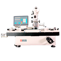
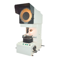
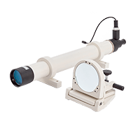
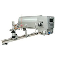
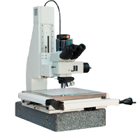
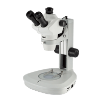
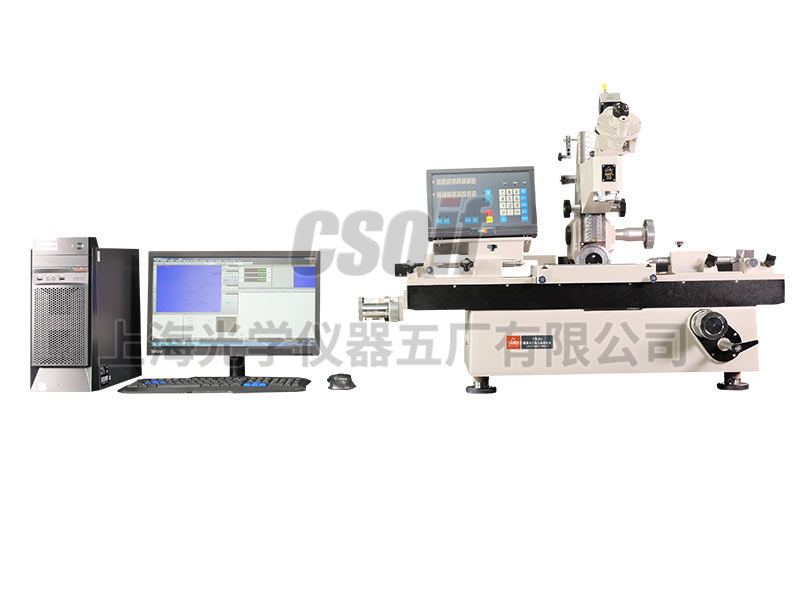
19JPC-V image-type universal tool microscope is a classic measuring instrument that our company has been producing for decades, and has obtained the patent of "Dual-channel Image Processing Universal Tool Microscope" (patent number: ZL201220504346.1). Retain all the original performance of the basic 19JC Wangong display, and add an image measurement system. The system uses a camera and a special optical objective lens to replace the human eye aiming, while retaining the eyepiece observation, and can save the video image. After the use of electronic amplification, the magnification of the Wangong display can be greatly improved, and the small workpiece can be easily observed and precisely measured.
The system is borrowed from the high-precision guide rails of Wangong Display, which can realize high-precision image measurement in the true sense.
use
19JPC-V image type universal tool microscope is a new generation of universal tool microscope applying computer-aided measurement, which can solve various complex measurement problems. It is difficult to measure geometric elements that cannot be directly observed in the field of view, such as the center of the circle, the midpoint, the intersection, the centerline and its mutual distance, the included angle, etc. on the 19JPC-V instrument. Can be solved. The instrument uses precision grating sensor, PC series microcomputer and data interface card to collect measurement data and camera system, uses image measurement software to process two-dimensional images of the computer, and displays and prints the measurement results. The instrument is easy to operate. The instrument uses both metric and imperial units of measurement. The calculation accuracy is 0.0001 mm and 0.0001 inch respectively. The instrument can automatically correct the assembly error of the slide guide rail of the worktable, which further improves the measurement accuracy.
Instrument Features
19JPC-V image type universal tool microscope uses computer image processing technology to process measurement data on the basis of 19JPC microcomputer type universal tool microscope. The image measurement software has a reticle aiming system. When the reticle encounters the measured target, it will flicker and change color to achieve accurate aiming. The instrument is a multi-purpose measuring instrument widely used in machinery, electronic manufacturing, and measurement testing. It can be used to measure the size, shape, angle and position of any part within the range. At the same time, it has two sets of reading systems of computer and digital display box.
Typical measurement objects:
Measure the shape of various formed parts such as templates, template turning tools, template milling cutters, dies and cams.
Measure the pitch diameter, minor diameter, pitch, and half angle of the external thread (thread plug gauge, screw and worm, etc.).
Measure the lead, profile and profile angle of gear hob.
Measure the position of the holes on the circuit board, the drilling die or the orifice plate, the symmetry of the keyway and other shape and position errors.
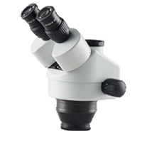
The main microscope is equipped with a variety of eyepieces and objective lenses, with a large field of view and clear imaging.
The instrument adopts photoelectric digital display and image technology, and uses precision grating ruler as the measuring element. Using advanced computer technology, the length signal collected by the grating digital display system is input into the computer in real time. There are special two-dimensional measurement software and image measurement software to process data and images according to user needs, and print out the results or graphics, which are accurate and efficient.
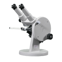
The main microscope can be tilted left and right for measuring spiral parts.
With non-contact measurement as the basic method, through and reflected illumination, parts with complex geometric shapes can be inspected.
The accessories are complete and widely used.
Instrument completeness
1. Host: digital universal tool microscope 19JC
2. Image 2D measurement software
3. Brand computers and color inkjet printers
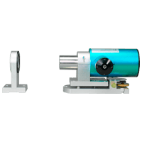
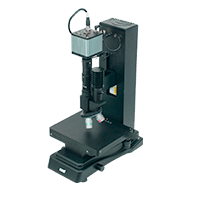
4. Image measurement components (cameras, frame capture cards)
Image 2D measurement software:
The main function
(1) Basic measurement functions: Using the WINDOWS interface, all operations are controlled by the mouse, which can measure points, lines, circles, arcs, angles, straightness, roundness, gears, threads, cams, etc.
(2) Calculation function: After the measurement process is over, the outline of the workpiece is displayed on the computer screen, and all kinds of calculation and evaluation are completed by the mouse.
(3) Graphic editing function: The contour diagram of the workpiece can be modified to generate a new contour diagram.
(4) Printing function: All measurement results, calculation results and workpiece contours are saved in the computer in the form of files, which can be called, edited and printed at any time.
(5) CAD interface: AUTOCAD can be called through the CAD interface, making full use of the functions of AUTOCAD.
It is a computer 2D image processing system specially developed for universal tool microscopes and measuring microscopes. The system uses computer image processing technology to organically integrate computer and optical instruments, making the measurement process more convenient and intuitive, and is an effective tool for intelligent measurement.
There is a reticle aiming system in the software. When the reticle encounters the measured target, it will flash and change color to achieve accurate aiming.
The software adopts the WINDOWS interface, and the image formed by the workpiece in the software is aimed at the point with a cross line, and the measurement of point, line, circle, arc, straightness, circularity, thread, etc. can be carried out. After the measurement process is over, the outline of the workpiece is displayed on the computer screen, and all kinds of calculation and evaluation are completed by the mouse. The measurement data can be printed out by the system printer, and the graphic file can also be converted into a file format that can be opened by CAD for editing.
Main technical specifications of universal tool microscope:
| X, Y coordinates | Measuring range: | 200×100㎜ | Resolution: 0.0001㎜ |
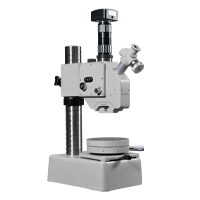
| aiming microscope | Lifting stroke: | 120㎜ | |
| Arm tilt range: | 15 degrees left and right | Graduation value: 10′ | |
| Illumination diaphragm adjustment range: | φ3~φ32㎜ | Grid value: 1㎜ | |
| goniometer eyepiece | Angle measurement range: | 360° | Graduation value: 1′ |
| Contour eyepiece | Angle measurement range: | ±7° | Graduation value: 10′ |
| Arc reticle: | Radius of curvature: | R0.1~100㎜ | |
| Threaded reticle: | common thread pitch | t = 0.25 - 6㎜ | |
| Trapezoidal thread pitch | T = 2 - 20㎜ | ||
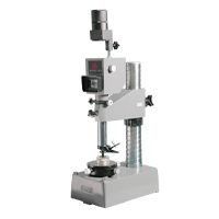
| Optical indexing head | Measuring range: | 360° | Graduation value: 1′ |
| Optical Positioner | Probe diameter: | Ф3±0.1㎜ (the limit verification error of the actual diameter value is not more than 0.5μm) | |
| Measuring force: | 0.1±0.03N | ||
| Maximum measuring depth | 15㎜ | ||
| glass workbench | Glass table size: | 215×130㎜ | |
| Thimble holder | Maximum clamping diameter: | Ф100㎜ | |
| Maximum clamping length: | When the diameter of the tested piece is ≤55㎜: 750㎜ | ||
| When the diameter of the test piece is greater than 55mm: 600mm | |||
| High thimble holder | Maximum clamping diameter: | Ф180㎜ | |
| Maximum clamping length: | 600㎜ | ||
| V-shaped frame | Left V-shaped frame front and rear adjustment range: | 5mm each | |
| Right V-shaped frame height adjustment range: | Up 15mm; Down 3mm | ||
| Maximum load 40kg | |||
2. Aiming microscope optical parameters
| Objective lens magnification flag value | 1× | 3× | 5× | |
| total magnification | with goniometric or profile eyepieces | 10× | 30× | 50× |
| with dual vision eyepieces | 15× | 42× | 65× | |
| object field of view | with goniometric or profile eyepieces | φ20 | φ6.6 | φ4 |
| with dual vision eyepieces | φ13 | φ4.7 | φ3 | |
| working distance | with goniometric or profile eyepieces | 81 | 90 | 65 |
| with dual vision eyepieces | 47 | 85 | 63 | |
3. Optical Objectives of Image Measurement Components:
| gain | total magnification | object field of view | working distance |
| 3× | 25× | Ф6 | 110 |
| 5× | 37× | Ф4 | 95 |
4. Instrument accuracy
Temperature requirements ⑴ The temperature of the working room should be 20±2 ℃; ⑵ The temperature change of the working room should be ≤0.5 ℃ per hour; ⑶ The temperature difference between the tested part and the instrument should be ≤0.5 ℃
Under the condition that the specified temperature requirements are met, the instrument has the following guarantees:
①When the X and Y coordinates are verified with a glass millimeter reticle, the maximum inaccuracy of the instrument: (1 + L / 100) μm where L = measurement length unit: mm, when the reticle of the instrument is corrected according to the correction table : X direction is not more than 0.0035mm, Y direction is not more than 0.0025
② Goniometer eyepiece Maximum inaccuracy of measuring angle: no more than 1′
③ Dual-image eyepiece Instability of combined image: no more than 0.0005mm, inaccuracy of combined image: no more than 0.001mm
④ Optical indexing head Maximum inaccuracy: no more than 30"
⑤ Optical positioner Measurement instability: no more than 0.001㎜, measurement inaccuracy: no more than 0.0015㎜
5. Instrument weight and dimensions
Mainframe net weight: about 250㎏
Mainframe dimensions: (X × Y × Z): 980 × 1020 × 640